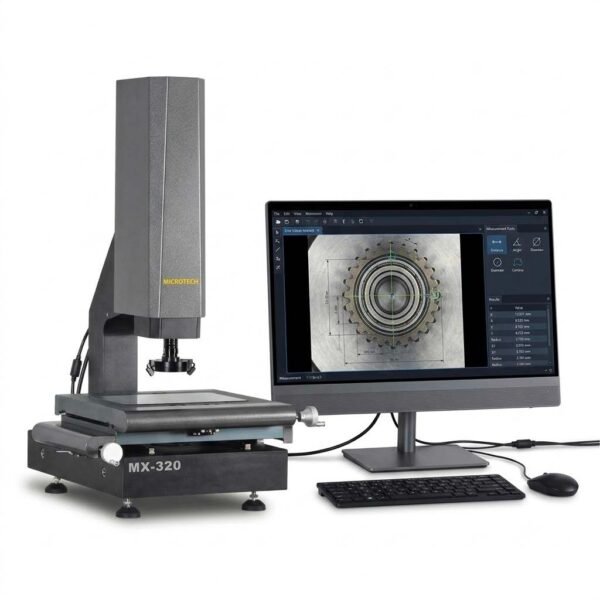

EvoMet Semi-Auto Vision Measuring Machine
300 × 200 × 200 mm Table Travel | 0.0005 mm Resolution | 2.1 + L/100 μm Accuracy | 18–195× Magnification | Motorized Z-Axis | 24″ Windows PC + 2D Measuring Software
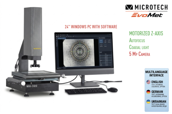
The SEMI-AUTO VISION MEASURING MACHINE MX-320 is an optical dimensional measuring system for inspection of visible 2D features, contours and geometry within a 300 × 200 × 200 mm measuring travel. Manual X/Y positioning is combined with a motorized Z-axis, 5 Mp autofocus camera, 6.5:1 manual zoom and three lighting systems. A supplied 24″ Windows PC with 2D measuring software and CAD comparison functions makes this version suitable for measurement tasks requiring magnified optical inspection and digital comparison with drawing geometry.
*taxes are not included
- Description
- Technical data
- PDF-Datasheet
Description
PRODUCT
The MX-320 is a semi-automatic vision measuring machine built on a granite base and column with precision HIWIN linear guides.
The measuring table provides 300 × 200 × 200 mm travel and supports workpieces up to 25 kg. The X and Y axes are positioned manually, while the Z-axis is motorized, allowing the optical system to move vertically for focusing and measurement.
The imaging system combines a 5 Mp high-resolution autofocus camera with 18–195× magnification provided by a 6.5:1 manual zoom. Electronic zoom feedback allows the software to identify the selected magnification automatically. The field of view ranges from 8.1 to 1.3 mm, with a 90 mm working distance.
The measuring system provides 0.0005 mm resolution and accuracy of 2.1 + L/100 μm.
OPTICAL SYSTEM AND LIGHTING
The MX-320 uses three illumination methods to adapt the image to different visible workpiece features:
- Programmable four-zone LED ring surface light
- LED bottom parallel light
- Coaxial light
The programmable ring light illuminates surfaces from above, while the bottom parallel light provides transmitted illumination through or around suitable workpiece geometry. Coaxial illumination directs light along the optical axis for features requiring axial surface illumination.
The combination allows the operator to select the illumination method that produces a clear optical boundary or surface feature for the measurement task.
2D MEASURING SOFTWARE
The machine is supplied with a 24″ Windows PC running MICROTECH 2D measuring software.
The software provides:
- 2D measurement functions
- CAD import
- CAD comparison
- Multilanguage interface
The interface supports English, German and Ukrainian.
CAD comparison allows measured optical geometry to be evaluated against imported design geometry, making the system particularly useful when inspection requires more than reading an isolated dimension and the relationship between the measured contour and its nominal geometry must also be checked.
WHERE IS IT USED AND WHAT TASKS DOES IT SOLVE?
The MX-320 is intended for dimensional inspection of components whose measurable geometry can be observed by the camera and evaluated in the 2D measuring software.
Small visible feature → difficult to inspect directly at normal viewing scale → 18–195× optical magnification.
The zoom optical system enlarges the measurement area so small edges and geometric details can be positioned and evaluated on the software display.
2D contour or profile → multiple points must be evaluated relative to nominal geometry → CAD import and comparison.
The measured image can be analyzed against imported CAD geometry instead of checking individual dimensions independently.
Feature requires accurate focus at different heights → manual focusing increases setup work → motorized Z-axis with autofocus camera.
Vertical optical positioning and autofocus support measurement of features located at different Z positions.
Edge visibility changes with surface or geometry → one illumination direction does not produce a clear boundary → ring, bottom and coaxial lighting.
Different illumination methods allow the optical image to be adapted to the feature being inspected.
Component requires movement between several measurement locations → measurement field is smaller than the complete workpiece → 300 × 200 mm X/Y table travel.
The measuring table allows different areas of the part to be brought into the camera field while maintaining the workpiece on the same measuring system.
WHAT PROBLEM DOES IT SOLVE?
Conventional contact instruments require physical access to each measuring surface and normally evaluate one dimension at a time. This becomes restrictive when the required feature is more effectively defined by a visible edge, contour or 2D geometry.
The MX-320 uses a high-resolution camera and magnified optical image to measure these features without requiring the measuring element to contact the observed edge.
The combination of 0.0005 mm resolution, motorized Z positioning, autofocus and controlled illuminationaddresses the practical difficulty of obtaining a clear, focused and measurable image.
For inspection against nominal part geometry, the CAD module additionally allows measured geometry to be compared directly with imported CAD data rather than relying only on manually interpreted individual readings.
HOW DOES IT WORK?
The workpiece is placed on the measuring table and positioned beneath the optical system using the manual X and Y controls.
The operator selects the required zoom level and illumination method. The software automatically identifies the zoom setting through electronic feedback, while the motorized Z-axis and autofocus camera establish the required image focus.
The camera captures the selected feature and displays it on the connected 24″ Windows PC. The operator then performs the required 2D measurement in the software.
For inspection against design geometry, CAD data can be imported and compared with the measured image or geometry. Different areas of the workpiece are inspected by repositioning the X/Y table and repeating the optical measurement sequence.
CONFIGURATION & OPTIONS
Standard configuration
MX-320 — Item No. 281010325
- Table travel: 300 × 200 × 200 mm
- Resolution: 0.0005 mm
- Accuracy: 2.1 + L/100 μm
- Magnification: 18–195×
- Manual zoom: 6.5:1
- Field of view: 8.1–1.3 mm
- Camera: 5 Mp autofocus
- Working distance: 90 mm
- Load capacity: 25 kg
- Manual X/Y axes
- Motorized Z-axis
- Four-zone LED surface illumination
- LED bottom parallel illumination
- Coaxial illumination
- 24″ Windows PC
- 2D measuring software with CAD import/comparison
Optional configuration
A Renishaw touch probe is available as an option, adding a contact probe configuration to the vision measuring system.
The delivery set includes the 24″ Windows PC with 2D measuring software and calibration protocol. A calibration certificate according to ISO/IEC 17025 / ILAC MRA is included.
Additional information
| Magnification | 18-195x |
|---|---|
| Table size | 300x200x200 |
| Resolution, mm | |
| Accuracy | 2,1+L/100 |
Related Products


FEATURED PRODUCTS
BEST SELLING PRODUCTS

DataMet Micron Computerized caliper e-Force Industry 4.0


CertiMet Big screen digital caliper IP54